DRV8302 - High performance BLDC driver
using Arduino UNO
DRV8302 is a high performance BLDC driver board capable of delivering 15A current continuously and 27A peak current. It has temperature and over-current protection, it has Back EMF and three phase current sensing and last but not the least it can be run using only 3PWM signals making it compatible with the SimpleFOClibrary.
BEWARE📢
Up to this moment (version 1.4.1 ) the library doesn't implement the current control loop. The motor torque is controlled via voltage directly. More info.
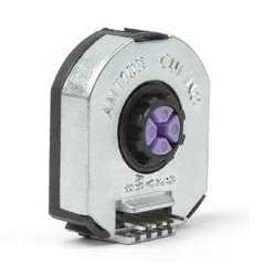
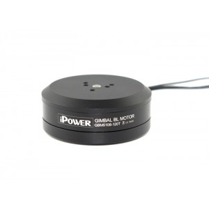
Here is an example hardware you might need for this project:


Here is an example of the connection scheme using the Arduino UNO:

DRV8302
- As any other BLDC driver supported with this library the board receives 3PWM signals: pwm
a,bandc. Connect them toINHA,INHBandINHC - Additionally connect the enable pin as well to
EN-GATEpin - To configure the BLDC driver we will need three pins (purple)
M_PWMwhenhighenables 3PWM mode (iflowthe board expects 6PWM signals)M_OCwhenlowenables over-current protectionOC_ADJanalog input adjusting the over-current limit - if you don’t care you can put it tohigh
- To read the fault signals we will need to read two pins (red)
nFAULTwhen inhighboard in fault statenOCTWwhen inhighover-current limit reached
Encoder
- Channels
AandBare connected to the external interrupt pins2and3 - If your encoder has
indexsignal you can connect it to any available digital pin, here we connected it to the pin4
Motor
- Motor phases
a,bandcare connected directly the board terminalsOUTA,OUTBandOUTC
Example connection

Arudino code 3PWM
The code to run the DRV8302 board with 3PWM is almost exactly the same as for the other low-power BLDC drivers. The only difference is the configuration procedure of the DRV8302.
Therefore let’s first start with the definitions of pins we are using with the board:
// DRV8302 pins connections
// don't forget to connect the common ground pin
#define INH_A 9
#define INH_B 10
#define INH_C 11
#define EN_GATE 8
#define M_PWM 6
#define M_OC 5
#define OC_ADJ 7
The variables INH_A, INH_B, INH_C and EN_GATE are supplied directly to the BLDCDriver3PWM class constructor.:
// driver instance
BLDCDriver3PWM driver = BLDCDriver3PWM(INH_A, INH_B, INH_C, EN_GATE);
The only other DRV8302 specific part of the code you need to do, is to add on the beginning of the setup() function:
// DRV8302 specific code
// M_OC  - enable over-current protection
pinMode(M_OC,OUTPUT);
digitalWrite(M_OC,LOW);
// M_PWM  - enable 3pwm mode
pinMode(M_PWM,OUTPUT);
digitalWrite(M_PWM,HIGH);
// OD_ADJ - set the maximum over-current limit possible
// Better option would be to use voltage divisor to set exact value
pinMode(OC_ADJ,OUTPUT);
digitalWrite(OC_ADJ,HIGH);
And the rest is the regular SimpleFOClibrary code for running BLDC motors.
Here is the full code of this project:
#include <SimpleFOC.h>

// DRV8302 pins connections
// don't forget to connect the common ground pin
#define INH_A 9
#define INH_B 10
#define INH_C 11
#define EN_GATE 8
#define M_PWM 6
#define M_OC 5
#define OC_ADJ 7

// motor instance
BLDCMotor motor = BLDCMotor(11);

// driver instance
BLDCDriver3PWM driver = BLDCDriver3PWM(INH_A, INH_B, INH_C, EN_GATE);

// encoder instance
Encoder encoder = Encoder(2, 3, 8192);
// channel A and B callbacks
void doA(){encoder.handleA();}
void doB(){encoder.handleB();}

// commander interface
Commander command = Commander(Serial);
void onMotor(char* cmd){ command.motor(&motor, cmd); }

void setup() {

  // initialize encoder sensor hardware
  encoder.init();
  encoder.enableInterrupts(doA, doB);
  // link the motor to the sensor
  motor.linkSensor(&encoder);

  // DRV8302 specific code
  // M_OC  - enable over-current protection
  pinMode(M_OC,OUTPUT);
  digitalWrite(M_OC,LOW);
  // M_PWM  - enable 3pwm mode
  pinMode(M_PWM,OUTPUT);
  digitalWrite(M_PWM,HIGH);
  // OD_ADJ - set the maximum over-current limit possible
  // Better option would be to use voltage divisor to set exact value
  pinMode(OC_ADJ,OUTPUT);
  digitalWrite(OC_ADJ,HIGH);

  // configure driver
  driver.voltage_power_supply = 12;
  driver.init();
  motor.linkDriver(&driver);

  // choose FOC modulation
  motor.foc_modulation = FOCModulationType::SpaceVectorPWM;

  // set control loop type to be used
  motor.controller = MotionControlType::torque;

  // controller configuration based on the control type
  motor.PID_velocity.P = 0.2;
  motor.PID_velocity.I = 20;

  // velocity low pass filtering time constant
  motor.LPF_velocity.Tf = 0.01;

  // angle loop controller
  motor.P_angle.P = 20;

  // angle loop velocity limit
  motor.velocity_limit = 50;
  // default voltage_power_supply
  motor.voltage_limit = 12;

  // use monitoring with serial for motor init
  // monitoring port
  Serial.begin(115200);
  // comment out if not needed
  motor.useMonitoring(Serial);

  // initialize motor
  motor.init();
  // align encoder and start FOC
  motor.initFOC();

  // set the initial target value
  motor.target = 2;

  // define the motor id
  command.add('M', onMotor, "motor");

  _delay(1000);
}


void loop() {
  // iterative setting FOC phase voltage
  motor.loopFOC();

  // iterative function setting the outer loop target
  // velocity, position or voltage
  // if target not set in parameter uses motor.target variable
  motor.move();

  // user communication
  command.run();
}
Arduino code 6PWM
The code to run the DRV8302 board with 6PWM we need to be careful to configure the pins correctly based on the microcontroller we are using.
An example fo Arduino uno pinout can be:
// DRV8302 pins connections
// don't forget to connect the common ground pin
#define INH_A 5
#define INH_B 9
#define INH_C 11
#define INL_A 6
#define INL_B 10
#define INL_C 3
#define EN_GATE 8
#define M_PWM 6
#define M_OC 5
#define OC_ADJ 7
For stm32 Nucleo board that pinout would not be suitable but this one would work:
// DRV8302 pins connections
// don't forget to connect the common ground pin
#define INH_A 7
#define INH_B 6
#define INH_C 5
#define INL_A 2
#define INL_B 3
#define INL_C 4
#define EN_GATE 8
#define M_PWM 9
#define M_OC 10
#define OC_ADJ 11
The variables INH_A, INH_B, INH_C,INL_A, INL_B, INHL_C and EN_GATE are supplied directly to the BLDCDriver6PWM class constructor.:
// driver instance
BLDCDriver6PWM driver = BLDCDriver6PWM(INH_A, INL_A, INH_B,INL_B, INH_C, INL_C, EN_GATE);
The only other DRV8302 specific part of the code you need to do, is to add on the beginning of the setup() function:
// DRV8302 specific code
// M_OC  - enable over-current protection
pinMode(M_OC,OUTPUT);
digitalWrite(M_OC,LOW);
// M_PWM  - enable 6pwm mode (can be left open)
pinMode(M_PWM,OUTPUT);
digitalWrite(M_PWM,LOW);
// OD_ADJ - set the maximum over-current limit possible
// Better option would be to use voltage divisor to set exact value
pinMode(OC_ADJ,OUTPUT);
digitalWrite(OC_ADJ,HIGH);
And the rest is the regular SimpleFOClibrary code for running BLDC motors.
Here is the full code of this project:
#include <SimpleFOC.h>

// DRV8302 pins connections
// don't forget to connect the common ground pin
#define INH_A 5
#define INH_B 9
#define INH_C 11
#define INL_A 6
#define INL_B 10
#define INL_C 3
#define EN_GATE 8
#define M_PWM 6
#define M_OC 5
#define OC_ADJ 7

// motor instance
BLDCMotor motor = BLDCMotor(11);

// driver instance
BLDCDriver6PWM driver = BLDCDriver6PWM(INH_A, INL_A, INH_B,INL_B, INH_C, INL_C, EN_GATE);

// encoder instance
Encoder encoder = Encoder(2, 3, 8192);
// channel A and B callbacks
void doA(){encoder.handleA();}
void doB(){encoder.handleB();}

// commander interface
Commander command = Commander(Serial);
void onMotor(char* cmd){ command.motor(&motor, cmd); }

void setup() {

  // initialize encoder sensor hardware
  encoder.init();
  encoder.enableInterrupts(doA, doB);
  // link the motor to the sensor
  motor.linkSensor(&encoder);

  // DRV8302 specific code
  // M_OC  - enable over-current protection
  pinMode(M_OC,OUTPUT);
  digitalWrite(M_OC,LOW);
  // M_PWM  - enable 6pwm mode (can be left open)
  pinMode(M_PWM,OUTPUT);
  digitalWrite(M_PWM,LOW);
  // OD_ADJ - set the maximum over-current limit possible
  // Better option would be to use voltage divisor to set exact value
  pinMode(OC_ADJ,OUTPUT);
  digitalWrite(OC_ADJ,HIGH);

  // configure driver
  driver.voltage_power_supply = 12;
  driver.init();
  motor.linkDriver(&driver);

  // choose FOC modulation
  motor.foc_modulation = FOCModulationType::SpaceVectorPWM;

  // set control loop type to be used
  motor.controller = MotionControlType::torque;

  // controller configuration based on the control type
  motor.PID_velocity.P = 0.2;
  motor.PID_velocity.I = 20;

  // velocity low pass filtering time constant
  motor.LPF_velocity.Tf = 0.01;

  // angle loop controller
  motor.P_angle.P = 20;

  // angle loop velocity limit
  motor.velocity_limit = 50;
  // default voltage_power_supply
  motor.voltage_limit = 12;

  // use monitoring with serial for motor init
  // monitoring port
  Serial.begin(115200);
  // comment out if not needed
  motor.useMonitoring(Serial);

  // initialize motor
  motor.init();
  // align encoder and start FOC
  motor.initFOC();

  // set the initial target value
  motor.target = 2;

  // define the motor id
  command.add('M', onMotor, "motor");

  _delay(1000);
}


void loop() {
  // iterative setting FOC phase voltage
  motor.loopFOC();

  // iterative function setting the outer loop target
  // velocity, position or voltage
  // if target not set in parameter uses motor.target variable
  motor.move();

  // user communication
  command.run();
}