Torque control using voltage
This torque control approach allows you to run the BLDC motor as it is simple DC motor, where you set the target voltage \(U_q\) to be set to the motor and the FOC algorithm calculates the necessary phase voltages \(u_a\) ,\(u_b\) and \(u_c\) for smooth operation. This mode is enabled by:
// voltage torque control mode
motor.torque_controller = TorqueControlType::voltage;
There are three different ways to control the torque of your motor using voltage requiring different knowledge about your motor mechanical parameters:
- Pure voltage control - no motor parameters needed
- Estimated current control - phase resistance required
- Estimated current control with Back-EMF compensation - required phase resistance and KV rating of the motor
Block diagrams of the three torque control techniques based on voltage control can be represented as:
Voltage control Voltage control + Phase resistance Voltage control + Phase resistance + KV rating
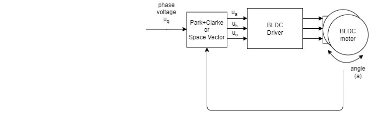

Pure voltage control
The voltage control algorithm reads the angle \(a\) from the position sensor and the gets target \(U_q\) voltage value from the user and using the FOC algorithm sets the appropriate \(u_a\), \(u_b\) and \(u_c\) voltages to the motor. FOC algorithm ensures that these voltages generate the magnetic force in the motor rotor exactly with 90 degree offset from its permanent magnetic field, which guarantees maximal torque, this is called commutation.
The assumption of the pure voltage control is that the torque generated (which is proportional to the current \(I = k \tau\)) in the motor is proportional the voltage as \(U_q\) set buy user. Maximal torque corresponds to the maximal \(U_q\) which is conditioned by the power supply voltage available, and the minimal torque is of course for \(U_q= 0\).
\[U_q \approx I = k\tau\]⚠️ Practical limitations
This torque control approach is the fastest and most simple one to setup by it does not limit the current in any way!
Expected motor behavior
If the user sets the desired voltage \(U_q\) of 0 Amps, the motor should not move and have some resistance, not too much, but more than when the motor is disconnected from the driver.
If you set a certain desired voltage \(U_g\) your motor should start moving and the velocity reached should be proportional to the voltage set \(U_q\). The behavior should be very similar to the DC motor controlled by changing the voltage on its wires.
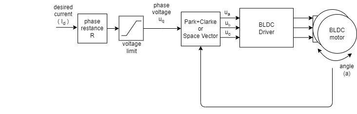
Voltage control with current estimation
Block diagram of this torque control strategy is as follows
If the user provides the phase resistance \(R\) value of the motor, the user can set the desired current \(I_d\) (that generates the desired torque \(I_d = k\tau_d\)) and the library will automatically calculate the appropriate voltage \(U_q\).
\[U_q = I_d R = (k\tau_d) R\]User can specify the phase resistance of the motor either through the constructor for example
// BLDCMotor(pole pair number, phase resistance)
BLDCMotor motor = BLDCMotor( 11, 2.5 );
or just setting the parameter:
motor.phase_resistance = 2.5; // ex. 2.5 Ohms
⚠️ Practical limitations
The resulting current in the motor can, in some cases, be higher than the desired current \(I_d\) but the order of the magnitude should be preserved. The better you know the phase resistance value \(R\) the better the current estimation will work. However, as the current \(I_d\) depends also of the back-emf voltage, not only the voltage \(U_q\), this current estimation strategy is very limited. The relationship \(U_q=I_dR\) is true only if the motor is not moving (no Back-EMF voltage generated). If the motor is moving the back-emf voltage generated will reduce the voltage set to the motor \( I_dR = U_q - U_{bemf}\). The practical limitation of this approach then will be that the desired current \(I_d\) is only set to the motor when it is static, and as soon as the motor moves the actual current set to the motor decreases.
Expected motor behavior
If the user sets the desired current of 0 Amps, the motor should not move and have some resistance, not too much, but more than when the motor is disconnected from the driver.
If you set a certain desired current \(I_d\) your motor should start moving and the velocity reached should be proportional to the current set \(I_d\).
For current \(I_d > 0\) motor does not move
If your desired current is set to some value that is not 0, but your motor does not move, your phase resistance value \(R\) is probably too low. Try increasing it.
Voltage control with current estimation and Back-EMF compensation
Block diagram of this torque control strategy is as follows
If the user provides the phase resistance \(R\) value and the motor’s \(KV\) rating of the motor, the user can set the desired current \(I_d\) (that generates the desired torque \(I_d = k\tau_d\)) directly. The library will automatically calculate the appropriate voltage \(U_q\) while compensating for the generated Back EMF voltage by keeping track of the motor velocity \(v\).
\[U_q = I_d R + U_{bemf}= (k\tau_d) R + \frac{v}{KV}\]User can specify the phase resistance and the KV rating of the motor either through the constructor for example
// BLDCMotor(pole pair number, phase resistance [Ohms], KV rating [rpm/V])
BLDCMotor motor = BLDCMotor( 11, 2.5, 120 );
RULE OF THUMB: KV value
KV rating of the motor is defined as speed of the motor in rpm with the set voltage \(U_q\) of 1 Volt. If you do not know your motor's KV rating you can easily measure it using the library. Run your motor int the voltage mode and set the target voltage to one 1V and read the motor velocity. SimpleFOClibrary shows that velocity in the rad/s so in order to convert it to the rpm you just need to multiply it by \(30/\pi \approx 10\).
As explained above as the Back-EMF constant of the motor is always a bit smaller than the inverse of the KV rating ( \(k_{bemf}<1/KV\) ), the rule of thumb is to set the KV rating 10-20% higher than the one given in the datasheet, or the one determined experimentally.
With the \(R\) and \(KV\) information the SimpleFOClibrary is able to estimate current set to the motor and the user will be able to control the motor torque, provided the motor parameters are correct (enough 😄).
⚠️ Practical limitations
Back-EMF voltage is defined as \(U_{bemf} = k_{bemf}v\) and calculating it based on the motor \(KV\) rating of the motor is just an approximation because the motor BEMF constant \(k_{bemf}\) is not exacly \(k_{bemf}=1/KV\). It can be shown that the back-emf constant is always somewhat smaller than the inverse of the KV rating: \[k_{bemf}<\frac{1}{KV}\]
Expected motor behavior
If the user sets the desired current of 0 Amps, the motor should have very low resistance, much lower than in the two torque control strategies above. The motor should feel like it is almost disconnected.
For current 0 motor moves
If your desired current is set to 0, but when you move your motor with your hand it continues moving on its own and does not come back to a complete stop, your \(KV\) value is too high. Try reducing it.
If you set a certain desired current \(I_d\) your motor should accelerate to its maximum velocity. The acceleration value is proportional to the motor torque and will be proportional to the current \(I_d\). So for larger currents your motor will accelerate faster and for the lower currents it will accelerate slower. But for the motor without load, regardless of set target current \(I_d\) the motor should reach its max velocity.
For current \(I_d > 0\) motor does not move
If your desired current is set to some value that is not 0, but your motor does not move, your phase resistance value \(R\) is probably too low. Try increasing it.
For more info about the theory of the torque control check the section Digging deeper section or go directly to torque control theory.
Torque control example code
A simple example of the voltage based torque control and setting the target current by serial command interface.
#include <SimpleFOC.h>

// BLDC motor & driver instance
BLDCMotor motor = BLDCMotor(11);
BLDCDriver3PWM driver = BLDCDriver3PWM(9, 5, 6, 8);

// encoder instance
Encoder encoder = Encoder(2, 3, 500);
// channel A and B callbacks
void doA(){encoder.handleA();}
void doB(){encoder.handleB();}

// instantiate the commander
Commander command = Commander(Serial);
void doMotor(char* cmd) { command.motor(&motor, cmd); }

void setup() {

  // initialize encoder sensor hardware
  encoder.init();
  encoder.enableInterrupts(doA, doB);
  // link the motor to the sensor
  motor.linkSensor(&encoder);

  // driver config
  // power supply voltage [V]
  driver.voltage_power_supply = 12;
  driver.init();
  // link driver
  motor.linkDriver(&driver);

  // set the torque control type
  motor.phase_resistance = 12.5; // 12.5 Ohms
  motor.torque_controller = TorqueControlType::voltage;
  // set motion control loop to be used
  motor.controller = MotionControlType::torque;

  // use monitoring with serial
  Serial.begin(115200);
  // comment out if not needed
  motor.useMonitoring(Serial);

  // initialize motor
  motor.init();
  // align sensor and start FOC
  motor.initFOC();

  // add target command M
  command.add('M', doMotor, "motor");

  Serial.println(F("Motor ready."));
  Serial.println(F("Set the target current using serial terminal:"));
  _delay(1000);
}

void loop() {

  // main FOC algorithm function
  motor.loopFOC();

  // Motion control function
  motor.move();

  // user communication
  command.run();
}