In-line current sensing
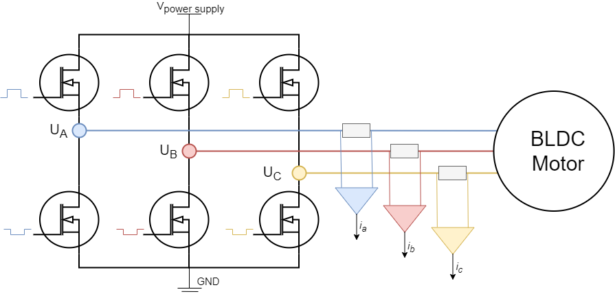
Inline current sensing technique is the simplest one to use and the most precise one. The shunt resistors are placed in-line with motor phases and the current measured on these shunt resistors will be motor phase current regardless of the state of the PWM duty cycle. This implementation is therefore very suitable for Arduino devices due to the fact that adc can be sampled at any time to read the current and the adc acquisition duration is as important as for the other current sensing approaches. The downside of this approach is the hardware, this current sensing architecture requirers high-precision bidirectional amplifiers with much better PWM rejection than the regular low-side or high-side amplifiers.
Step 1. Hardware configuration
// InlineCurrentSensor constructor
//  - shunt_resistor  - shunt resistor value
//  - gain  - current-sense op-amp gain
//  - phA   - A phase adc pin
//  - phB   - B phase adc pin
//  - phC   - C phase adc pin (optional)
InlineCurrentSense current_sense  = InlineCurrentSense(0.01, 20, A0, A1, A2);
To instantiate the inline current sensor using the SimpleFOClibrary just create an instance of the class InlineCurrentSense. This class takes as a parameter shunt resistance value shunt_resistor, amplification gain gain and two or three ADC channel pins depending on the available measuring hardware that you might have. It is important to specify right adc channels for right driver/motor phase. So if your pin A0 measures the phase current A and pin A1 measures the phase current B make sure to put provide them to the constructor in that order.
Field Oriented Control algorithm can run with both 2 or 3 phase current measurements.
The constructor of the InlineCurrentSense class only allows you to specify one shunt resistor value and one amplification gain. If your hardware configuration has different shunt/amp values for different phases you can specify them by changing the gain_x attribute:
// default values of per phase gains
current_sense.gain_a = 1.0 / shunt_resistor / gain;
current_sense.gain_b = 1.0 / shunt_resistor / gain;
current_sense.gain_c = 1.0 / shunt_resistor / gain;
For example Arduino SimpleFOCShield v2 has the phase B of the current sensing inverted. So in its case you can specify:
// inverse current sensing gain on phase b
current_sense.gain_b *= -1;
Once the current sense has been created it can be initialised. This init() function configures the ADC hardware for reading and finds the zero offsets of the ADC for each channel.
// init current sense
current_sense.init();
Once when your current sense has been intialised and calibrated you can start measuring the currents!
Using the current sense with FOC algorithm
To use the InlineCurrentSense with the FOC algorithm all you need to do is to add it to link it with the BLDCMotor you wish to use it with:
// link motor and current sense
motor.linkCurrentSense(¤t_sense);
The BLDCMotor class in the initFOC() function where it aligns all the sensors, will align the InlineCurrentSense with the BLDCDriver that is linked to the motor.
// prepare sensors for FOC
motor.initFOC();
Function initFOC() will call two current sense class functions that are important:
current_sense.driverSync(...)current_sense.driverAlign(...)
Driver synchronisation driverSync(...)
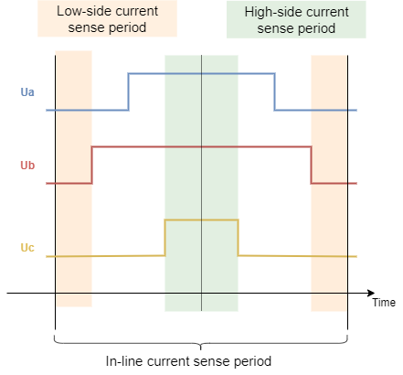
Since the Inline current sensing technique does not require triggering of particular events for ADC acquisition the driverSync() function does nothing really. This function will be very ipmportant for low-side and high-side current sensing as shown on the figure above.
Alignment with the motor phases driverAlign(...)
The alignment is done by calling the function:
current_sense.driverAlign(&driver, voltage_sensor_align);
This function applies using the driver instance applies the voltage to each of the phases and checks if the measured currents correspond to the directions of the applied voltages. This alignment procedure is able to correct for:
- Incorrect order of adc pins
- Incorrect gain sign
If monitoring is enabled for the motor during the initFOC the monitor will display the alignment status:
0- fail1- success and nothing changed2- success but pins reconfigured3- success but gains inverted4- success but pins reconfigured and gains inverted
If you are sure in your configuration and if you wish to skip the alignment procedure you can specify set the skip_align flag before calling motor.initFOC():
// skip alignment procedure
current_sense.skip_align = true;
For example Arduino SimpleFOCShield v2, you would have a code similar to this:
// invert phase b gain
current_sense.gain_b *=-1;
// skip alignment
current_sense.skip_align = true;
...
// align all sensors
motor.initFOC();
Standalone current sense
To use your inline current sensor as a stand-alone sensor after you have configured the hardware and calibrated it you can read the phase currents by calling:
PhaseCurrent_s current = current_sense.getPhaseCurrents();
This function returns the PhaseCurrent_s structure that which has three variables a, b and c. So you can print them out for example;
Serial.println(current.a);
Serial.println(current.b);
Serial.println(current.c); // 0 if only two currents mode
If you are using only two phase current measurements in your InlineCurrentSense, it will return the third current current.c equal to 0.
Sometimes the phase currents are hard to interpret, therefore this current sense class enables you to read the transformed current vector magnitude. The absolute DC current the motor is drawing.
float current_mag = current_sense.getDCCurrent();
Futhermore if you have an access to the position sensor of the motor connected to the driver you can get signed value of the DC current the motor is drawing by providing it to the getDCCurrent method.
float current = current_sense.getDCCurrent(motor_electrical_angle);
Finally if you have the access to the motor position sensor you current sense class will be able to tell you the FOC currents D and Q that your motor is drawing.
DQCurrent_s current = current_sense.getFOCCurrents(motor_electrical_angle);
This function returns the DQCurrent_s structure which has two variables, d and q. You can print them out for example:
Serial.println(current.d);
Serial.println(current.q);
Example code
Here is a simple example of a inline current sense as a stand-alone sensor using the SimpleFOClibrary and SimpleFOCShield v2.
#include <SimpleFOC.h>

// current sensor
// shunt resistor value
// gain value
// pins phase A,B
InlineCurrentSense current_sense = InlineCurrentSense(0.01, 50.0, A0, A2);

void setup() {
  // initialise the current sensing
  current_sense.init();

  // for SimpleFOCShield v2.01/v2.0.2
  current_sense.gain_b *= -1;

  Serial.begin(115200);
  Serial.println("Current sense ready.");
}

void loop() {

    PhaseCurrent_s currents = current_sense.getPhaseCurrents();
    float current_magnitude = current_sense.getCurrent();

    Serial.print(currents.a*1000); // milli Amps
    Serial.print("\t");
    Serial.print(currents.b*1000); // milli Amps
    Serial.print("\t");
    Serial.print(currents.c*1000); // milli Amps
    Serial.print("\t");
    Serial.println(current_magnitude*1000); // milli Amps
}