Arduino UNO + L6234 driver
Drotek’s L6234 breakout board is a very minimalistic 3-phase BLDC motor driver and is very suitable for jump-starting your FOC experience. Here we show two example connections using this board and Arduino UNO:
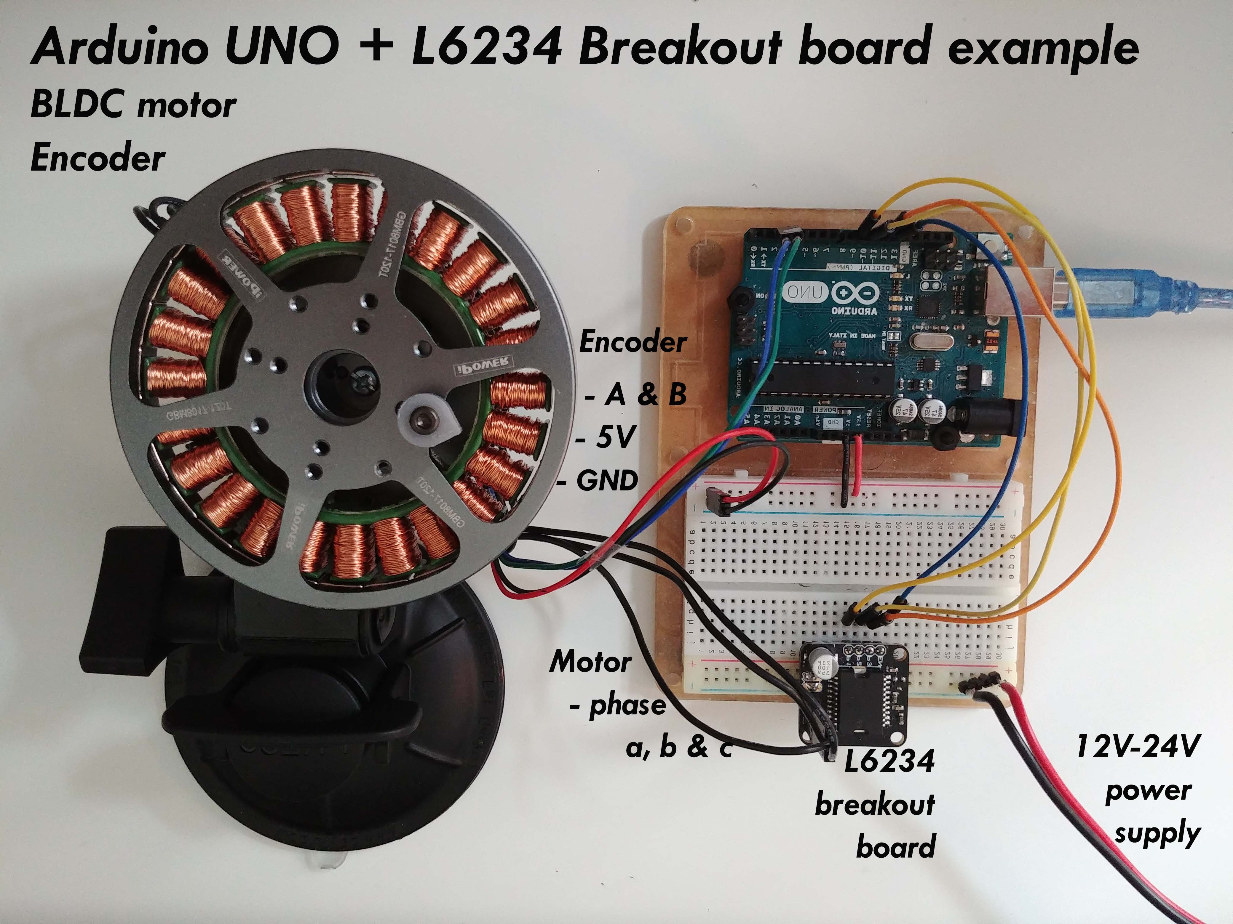
Encoder example

Encoder
- Encoder channels
AandBare connected to the Arduino’s external interrupt pins2and3. - Optionally if your encoder has
indexsignal you can connect it to any available pin, figure shows pin4.- For Arduino UNO and similar broads which don’t have 3 hardware interrupts, if you can choose, preferably connect index pin to pins
A0-A5due to the interrupt routine, it will have better performance (but any other pin will work as well). - Otherwise if you are using different board and have 3 hardware interrupt pins connect the index pin to one of them.
- For Arduino UNO and similar broads which don’t have 3 hardware interrupts, if you can choose, preferably connect index pin to pins
L6234 breakout board
- Connected to the arduino pins
9,10and11(you can use also pins5and6). - Additionally you can connect the
enablepin to the any digital pin of the arduino the picture shows pin8but this is optional. You can connect the driver enable directly to 5v. - Make sure you connect the common ground of the power supply and your Arduino
Motor
- Motor phases
a,bandcare connected directly to the driver outputs
Example connection
Magnetic sensor AS5048 example

Magnetic sensor
- Magnetic sensor’s (AS5048) SPI interface signals
SCK,MISOandMOSIare connected to the Arduino’sSPIpins (Arduino UNO13,12and11).- If the application requires more than one sensor all of them are connected to the same pins of the Arduino.
- The
chip selectpin is connected to the desired pin. Each sensor connected to the same Arduino has to have unique chip select pin.
L6234 breakout board
- Connected to the arduino pins
3,5and6(you can use also pin9and10, but pin11is taken by the SPI interface). - Additionally you can connect the
enablepin to the any digital pin of the arduino the picture shows pin2but this is optional. You can connect the driver enable directly to 5v. - Make sure you connect the common ground of the power supply and your Arduino
Motor
- Motor phases
a,bandcare connected directly to the driver outputs
Alignment
Motor phasesa,b,cand encoder channelsAandBand the magnetic sensor counting direction have to be oriented right for the algorithm to work. But don't worry about it too much. Connect it initially as you wish and then if the motor locks in place inverseaandbof the motor, that should be enough.