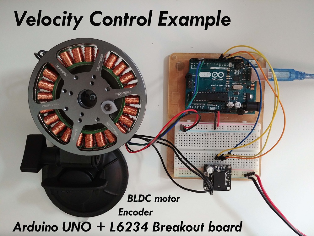
Velocity control loop
This control loop allows you to spin your motor with desired velocity. This mode is enabled by:
// set velocity motion control loop
motor.controller = MotionControlType::velocity;
You can test this algorithm by running the examples in the motion_control/velocity_motion_control/ folder.
How it works
The velocity control closes the control loop around the torque control, regardless which one it is. If it is the voltage mode without phase resistance set, the velocity motion control will set the the torque command using the voltage Uq::

And if it is any of the current torque control modes (FOC or DC current) or voltage mode with provided phase resistance, the velocity motion control will be setting the target current iq:

The velocity control is created by adding a PID velocity controller to the torque control loop. PID controller reads the motor velocity v, filters it to vf and sets the torque target (uq voltage or iq current) to the torque control loop in a such manner that it reaches and maintains the target velocity vd, set by the user.
Controller parameters
To tune this control loop you can set the parameters to both angle PID controller and velocity measurement low pass filter.
// controller configuration based on the control type
// velocity PID controller parameters
// default P=0.5 I = 10 D = 0
motor.PID_velocity.P = 0.2;
motor.PID_velocity.I = 20;
motor.PID_velocity.D = 0.001;
// jerk control using voltage voltage ramp
// default value is 300 volts per sec  ~ 0.3V per millisecond
motor.PID_velocity.output_ramp = 1000;

// velocity low pass filtering
// default 5ms - try different values to see what is the best.
// the lower the less filtered
motor.LPF_velocity.Tf = 0.01;

// setting the limits
// either voltage
motor.voltage_limit = 10; // Volts - default driver.voltage_limit
// of current
motor.current_limit = 2; // Amps - default 0.2Amps
The parameters of the PID controller are proportional gain P, integral gain I, derivative gain D and output_ramp.
- In general by raising the proportional gain
Pyour motor controller will be more reactive, but too much will make it unstable. Setting it to0will disable the proportional part of the controller. - The same goes for integral gain
Ithe higher it is the faster motors reaction to disturbance will be, but too large value will make it unstable. Setting it to0will disable the integral part of the controller. - The derivative part of the controller
Dis usually the hardest to set therefore the recommendation is to set it to0and tune thePandIfirst. Once when they are tuned and if you have an overshoot you add a bit ofDcomponent to cancel it. - The
output_rampvalue it intended to reduce the maximal change of the voltage value which is sent to the motor. The higher the value the PI controller will be able to change faster the Uq value. The lower the value the smaller the possible change and the less responsive your controller becomes. The value of this parameter is set to beVolts per second[V/sor in other words how many volts can your controller raise the voltage in one time unit. If you set yourvoltage_rampvalue to10 V/s, and on average your control loop will run each1ms. Your controller will be able to change the Uq value each time10[V/s]*0.001[s] = 0.01Vwhat is not a lot.
Additionally, in order to smooth out the velocity measurement Simple FOC library has implemented the velocity low pass filter. Low pass filters are standard form of signal smoothing, and it only has one parameter - filtering time constant Tf.
- The lower the value the less influence the filter has. If you put
Tfto0you basically remove the filter completely. The exactTfvalue for specific implementation is hard guess in advance, but in general the range of values ofTfwill be somewhere form0to0.5seconds.
The voltage_limit parameter is intended if, for some reason, you wish to limit the voltage that can be sent to your motor.
In order to get optimal performance you will have to fiddle a bit with with the parameters. 😁
For more theory about this approach and the source code documentation check the digging deeper section.
Velocity motion control example
Here is one basic example of the velocity motion control with the voltage mode torque control with the complete configuration. The program will set the target velocity of 2 RAD/s and maintain it (resist disturbances) .
#include <SimpleFOC.h>

// motor instance
BLDCMotor motor = BLDCMotor( pole_pairs , phase_resistance );
// driver instance
BLDCDriver3PWM driver = BLDCDriver3PWM(pwmA, pwmB, pwmC, enable);

// Magnetic sensor instance
MagneticSensorSPI AS5x4x = MagneticSensorSPI(chip_select, 14, 0x3FFF);

void setup() {

  // initialize magnetic sensor hardware
  AS5x4x.init();
  // link the motor to the sensor
  motor.linkSensor(&AS5x4x);

  // driver config
  driver.init();
  motor.linkDriver(&driver);

  // set motion control loop to be used
  motor.controller = MotionControlType::velocity;

  // controller configuration
  // default parameters in defaults.h

  // controller configuration based on the control type
  // velocity PID controller parameters
  // default P=0.5 I = 10 D =0
  motor.PID_velocity.P = 0.2;
  motor.PID_velocity.I = 20;
  motor.PID_velocity.D = 0.001;
  // jerk control using voltage voltage ramp
  // default value is 300 volts per sec  ~ 0.3V per millisecond
  motor.PID_velocity.output_ramp = 1000;

  // velocity low pass filtering
  // default 5ms - try different values to see what is the best.
  // the lower the less filtered
  motor.LPF_velocity.Tf = 0.01;

  // since the phase resistance is provided we set the current limit not voltage
  // default 0.2
  motor.current_limit = 1; // Amps

  // use monitoring with serial
  Serial.begin(115200);
  // comment out if not needed
  motor.useMonitoring(Serial);

  // initialize motor
  motor.init();
  // align sensor and start FOC
  motor.initFOC();

  Serial.println("Motor ready.");
  _delay(1000);
}

// velocity set point variable
float target_velocity = 2; // 2Rad/s ~ 20rpm

void loop() {
  // main FOC algorithm function
  motor.loopFOC();

  // Motion control function
  motor.move(target_velocity);
}
Project examples
Here are two project examples which use velocity motion control and describe the full hardware + software setup needed.
Find more projects in the example projects section.


