Low-side current sensing
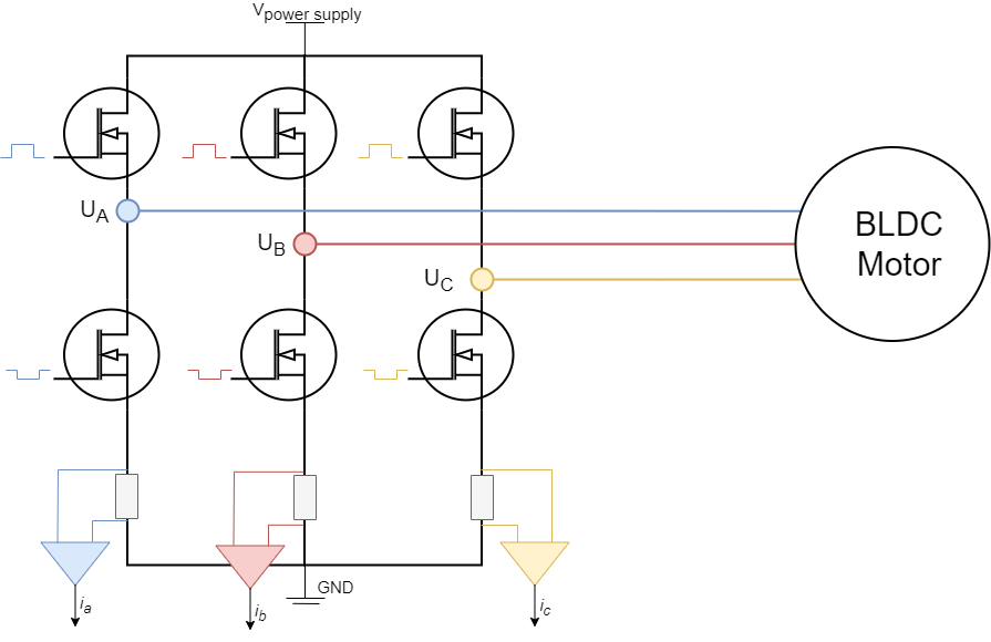
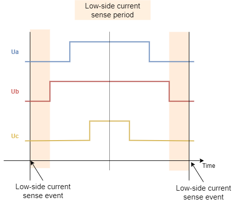
Low-side current sensing is probably the most common current sensing technique. The main reason why is because it does not require neither high-performance PWM rejection current sense amplifiers (as inline does) neither high-voltage supporting amplifiers (as high-side does). The shunt resistors are always placed in between low side mosfets and the ground making sure that the amplifiers always have very low voltages on their terminals. The main drawback of this approach is that, since the current passing through the shunt resistors is phase current only if the corresponding low side mosfet is ON, we can only measure it in those moments. The PWM frequency is usually 20 to 50 kHz, which means that the low-side mosfets turns on and off 20,000 to 50,000 times per second, therefore the synchronization in between PWM setting and ADC acquisition is very very important.
Low side current sensing for all the architectures is on our road-map and we are actively working on it. The main issue at the moment is very hardware specific synchronisation procedure of the PWM generation and ADC triggering. Therefore we are attacking one MCU architecture at the time. 😃
Step 1. Hardware configuration
// LowsideCurrentSense constructor
//  - shunt_resistor  - shunt resistor value
//  - gain  - current-sense op-amp gain
//  - phA   - A phase adc pin
//  - phB   - B phase adc pin
//  - phC   - C phase adc pin (optional)
LowsideCurrentSense current_sense  = LowsideCurrentSense(0.01, 20, A0, A1, A2);
To instantiate the low-side current sensor using the SimpleFOClibrary just create an instance of the class LowsideCurrentSense. This class takes as a parameter shunt resistance value shunt_resistor, amplification gain gain and two or three ADC channel pins depending on the available measuring hardware that you might have. It is important to specify right adc channels for right driver/motor phase. So if your pin A0 measures the phase current A and pin A1 measures the phase current B make sure to put provide them to the constructor in that order.
Field Oriented Control algorithm can run with both 2 or 3 phase current measurements.
The constructor of the LowsideCurrentSense class only allows you to specify one shunt resistor value and one amplification gain. If your hardware configuration has different shunt/amp values for different phases you can specify them by changing the gain_x attribute:
// default values of per phase gains
current_sense.gain_a = 1.0 / shunt_resistor / gain;
current_sense.gain_b = 1.0 / shunt_resistor / gain;
current_sense.gain_c = 1.0 / shunt_resistor / gain;
For example AliExpress DRV8302 board has all the current sensing phases inverted inverted. So in its case you can specify:
// inverse current sensing gain
current_sense.gain_a *= -1;
current_sense.gain_b *= -1;
current_sense.gain_c *= -1;
Once the current sense has been created it can be initialised. This init() function configures the ADC hardware for reading and finds the zero offsets of the ADC for each channel.
// init current sense
current_sense.init();
Once when your current sense has been intialised and calibrated you can start measuring the currents!
Using the current sense with FOC algorithm
To use the LowsideCurrentSense with the FOC algorithm all you need to do is to add it to link it with the BLDCMotor you wish to use it with:
// link motor and current sense
motor.linkCurrentSense(¤t_sense);
The BLDCMotor class in the initFOC() function where it aligns all the sensors, will align the LowsideCurrentSense with the BLDCDriver that is linked to the motor.
// prepare sensors for FOC
motor.initFOC();
Function initFOC() will call two current sense class functions that are important:
current_sense.driverSync(...)current_sense.driverAlign(...)
Driver synchronisation driverSync(...)
Since the low-side current sensing technique requires triggering of the ADC acquisition exactly when all the low side mosfets are ON (when all the phases are grounded) the driverSync() synchronises the driver PWM with ADC conversion.
Alignment with the motor phases driverAlign(...)
The alignment is done by calling the function:
current_sense.driverAlign(&driver, voltage_sensor_align);
This function applies using the driver instance applies the voltage to each of the phases and checks if the measured currents correspond to the directions of the applied voltages. This alignment procedure is able to correct for:
- Incorrect order of adc pins
- Incorrect gain sign
If monitoring is enabled for the motor during the initFOC the monitor will display the alignment status:
0- fail1- success and nothing changed2- success but pins reconfigured3- success but gains inverted4- success but pins reconfigured and gains inverted
If you are sure in your configuration and if you wish to skip the alignment procedure you can specify set the skip_align flag before calling motor.initFOC():
// skip alignment procedure
current_sense.skip_align = true;
For example AliExpress DRV8302 board , you would have a code similar to this:
// invert phase b gain
current_sense.gain_a *=-1;
current_sense.gain_b *=-1;
current_sense.gain_c *=-1;
// skip alignment
current_sense.skip_align = true;
...
// align all sensors
motor.initFOC();
Standalone current sense
Since the low-side current sense has to be synchornised with PWM of a driver of interest it does not make sense to use it as a stand-alone sensor. But once when you liked the current sense with the BLDCMotor you can use it to get more info about your phase currents, overall current magnitude and DQ currents.
Reading the phase currents can be done by calling:
PhaseCurrent_s current = current_sense.getPhaseCurrents();
This function returns the PhaseCurrent_s structure that which has three variables a, b and c. So you can print them out for example;
Serial.println(current.a);
Serial.println(current.b);
Serial.println(current.c); // 0 if only two currents mode
If you are using only two phase current measurements in your LowsideCurrentSense, it will return the third current current.c equal to 0.
Sometimes the phase currents are hard to interpret, therefore this current sense class enables you to read the transformed current vector magnitude. The absolute DC current the motor is drawing.
float current_mag = current_sense.getDCCurrent();
Futhermore if you have an access to the position sensor of the motor connected to the driver you can get signed value of the DC current the motor is drawing by providing it to the getDCCurrent method.
float current = current_sense.getDCCurrent(motor_electrical_angle);
Finally if you have the access to the motor position sensor you current sense class will be able to tell you the FOC currents D and Q that your motor is drawing.
DQCurrent_s current = current_sense.getFOCCurrents(motor_electrical_angle);
This function returns the DQCurrent_s structure which has two variables, d and q. You can print them out for example:
Serial.println(current.d);
Serial.println(current.q);
Example code
Here is a simple example of a low-side current sense using the SimpleFOClibrary and to read the motor currents directly.
#include <SimpleFOC.h>
// define the motor and the driver
motor = ...
driver = ...
// current sensor
// shunt resistor value
// gain value
// pins phase A,B
LowsideCurrentSense current_sense = LowsideCurrentSense(0.01, 50.0, A0, A2);
void setup() {
// init driver
driver.init()
...
// initialise the current sensing
current_sense.init();
motor.linkCurrentSense(¤t_sense);
...
motor.initFOC();
...
Serial.begin(115200);
Serial.println("Setup ready.");
}
void loop() {
// foc and motion controls
motor.loopFOC();
motor.move();
PhaseCurrent_s currents = current_sense.getPhaseCurrents();
float current_magnitude = current_sense.getDCCurrent();
Serial.print(currents.a*1000); // milli Amps
Serial.print("\t");
Serial.print(currents.b*1000); // milli Amps
Serial.print("\t");
Serial.print(currents.c*1000); // milli Amps
Serial.print("\t");
Serial.println(current_magnitude*1000); // milli Amps
}